Part VII
Production of MSB-23 (First Boat)
Production of MSB-23
Mold Preparation
On the inside of the female mold, longitudinal lines were drawn which divided each half of the mold surface into four parts. Marks were made along each of these lines and along the mold E and sheer lines at the proper intervals to determine the position of the leading edge of each ply of the outer skin shingle layup. Following the application of these marks, the mold surface was waxed and the parting film applied. A gel coat of standard laminating resin was brushed on as a protection for the parting film.
The Outer Skin
The 7-ply outer skin was applied transversely in a shingle layup, using the marks provided on the mold surface to position each ply. Each ply covered half the mold girth and the mold E was overlapped in such a manner that a 14-ply doubled area 10" wide was provided along the E, tapering in 7" to the 7-ply thickness on either side.
Cloth used in hull laminates was impregnated in a machine provided with suitable supports for rolls of dry and impregnated cloth, a resin trough equipped with submerged guide rollers, and four scraper bars through which the cloth was drawn before being re-rolled at the top of the machine. The impregnated cloth was allowed to soak in the roll for a short period of time and was then cut into suitable lengths for application to the hull laminate. These pieces were rolled up on lengths of two-inch aluminum pipe and then carried to the job and unrolled in place on the laminate in progress.
Layup was begun simultaneously at the bow and the stern and a joining was to be accomplished forward of amidships. A considerable reinforcing layup was provided as a part of the stern which involved a great deal of cloth cutting and proved to be rather time-consuming because of the cramped working space in the forward port of the mold. See photograph A45.
In general, layup of the outer skin proceeded without incident. A minor problem was the tendency of the selvage edge of each ply of cloth to lift away from the layup. Cutting into the selvage at intervals minimized this effect.
While the quality of the layup was satisfactory, the pounds per manhour rate was low due to the awkwardness of working inside the female mold, particularly in the bow.
Core Material and Internal Reinforcements
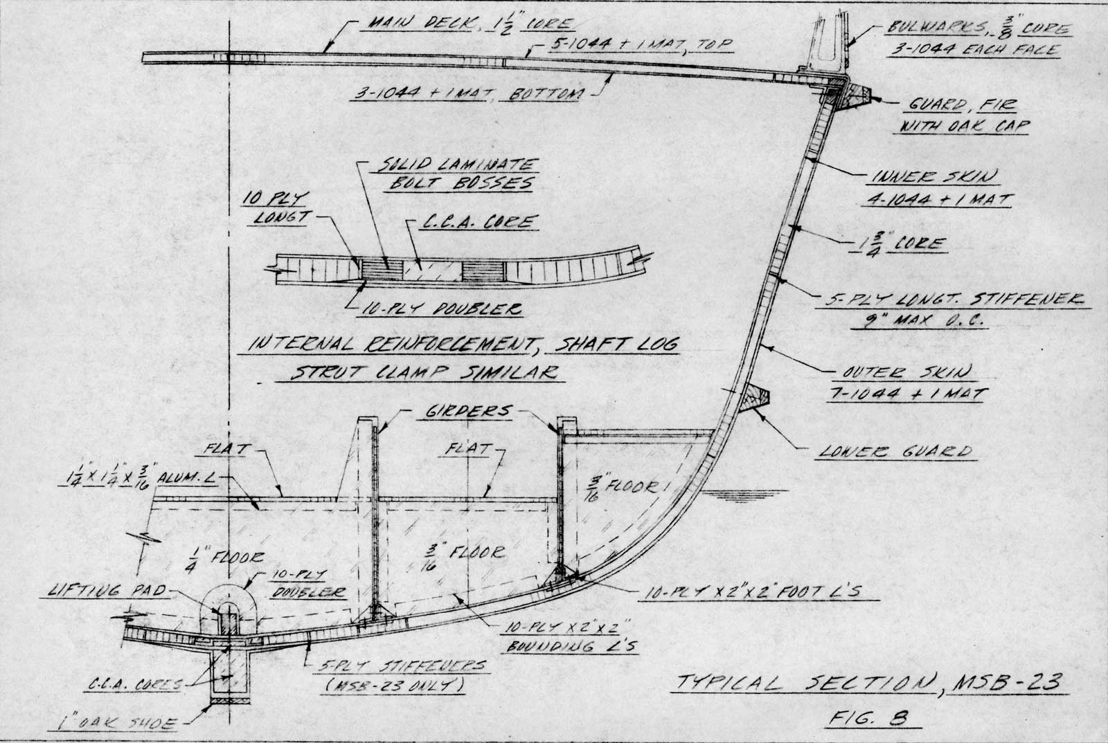
After the outer skin layup was complete, the first step was to install the internal reinforcements. These were provided between the inner and outer skins as additional reinforcement along the hull E and in way of shaft logs and strut and V-strut palms, and were included both to stiffen the hull in these areas and to provide bossing to resist the compressive stresses of thru-bolts holding the struts, etc. Details of these reinforcements are shown in Fig. 8, page 47.
When the major internal reinforcements were in place, preparations for the installation of the honeycomb with attendant flat bar longitudinal stiffeners were made.
Before installation of honeycomb was begun the hull was lined off in accordance with the appropriate working plans and the honeycomb cut and fitted for each side of the hull. The cut honeycomb was then marked and the pieces stored pending installation. The marking and handling system used with this cut honeycomb proved to be inadequate with the result that considerable confusion and loss of time ensued when many of the honeycomb planks could not be identified for final installation.
The bond of the honeycomb to the outer skin, 1 ply of unimpregnated 4 1/2 oz mat was first laid down, the honeycomb was then placed over the mat and the whole layup vacuum bagged to assure continued intimate contact with the outer skin until cured. In general, the honeycomb was placed one longitudinal course at a time, working outward from the hull E.
From the beginning of honeycomb installation, vacuum bag performance was faulty, and the result of continued poor bonding became progressively worse.
When honeycomb installation was about 25% complete, close inspection showed that over half of the honeycomb was poorly bonded. Some of this honeycomb was cured in place by injection of a filled resin into the bottoms of enough adjacent cells to attain satisfactory bond strength. The remainder of the poorly bonded honeycomb was removed and later replaced. Meanwhile, the vacuum bagging process was revised and provisions made to minimize the effects of air leaks which had been inadvertently built into the partially completed structure. This was accomplished through insertion of snug-fitting C.C.A. dowels and filled resin into rows of adjacent honeycomb cells so that continuous air stops were formed across the honeycomb already in place. Vacuum bags could then be sealed to these air stops. The remaining honeycomb installation, while always somewhat precarious, was accomplished without further need for major repairs.
When honeycomb installation was complete, doublers were laid up in way of each girder to take the fastenings from the girder-foot bounding angles to the hull. The honeycomb and longitudinal stiffeners were then ground and sanded to remove irregularities in preparation for the application of the bonding layer of the inner skin.
The Inner Bonding Layer
The bonding layer for the inner skin consisted of 1 ply of 1 1/2 oz mat with an overlying ply of 10/44 cloth which served to stabilize the mat during impregnation, handling, and application to the honeycomb. A vacuum bag was used to maintain contact, utilizing air stops mentioned above which had been provided in the hull to assist bagging of the honeycomb. See photograph A85. Application of the bonding layer proceeded without incident.
Internal Structural Components
After the outer skin of the hull had been completed, part of the shop force had been assigned to production of internal components - bulkheads, girders, flats and deck beams.
Bulkheads
Bulkheads were of sandwich construction, using 1-3/4" cotton honeycomb and with 3 plies of 10/44 cloth and 1 ply of mat each face. Vertical flat bar stiffeners were provided in the core and were spaced from 9" to 14" on centers, depending on the bulkhead, and C.C.A. fillers were provided in way of girder - bulkhead connections. Bulkhead panels were made on a molding table provided for the purpose and sufficient oversize was included to allow cutting to fit the hull.
Girders
Longitudinal girder sections were fabricated in a separate area from the hull layup. Girder sections consisted of a vertical web of 3/4" sandwich construction using 1/8" skins and the usual bonding ply of mat, topped by a 3-3/4" flange of solid laminate 3/8" thick. See Fig. 7, page 34. Vertical stiffeners were bonded to the web and flange at 12" intervals. Fabrication took place on tables provided with flange molding strips. Girder sections were to be intercostal and were made large enough to allow for cutting to template.
Flats
Walking flats were made up as sandwich panels using 5/8" honeycomb with two plies of 10/44 cloth top and bottom. No mat was used in fabrication of the flats. Crew's quarters flats had 1-1/4" honeycomb with three plies of 10/44 cloth in the top skin and two plies in the bottom skin. See photographs A68 and A69.
Deck Beams and Longitudinals
Deck beams were made up box-section using a C.C.A. core wrapped with 10/44 cloth to give the desired laminate thickness. See photograph A67. Prior to wrapping of the laminate, the core was vacuum bagged to a camber mold with one ply of cloth top and bottom. See photograph A66. This served to strengthen the otherwise fragile core and helped hold the camber of the beam during wrapping. Following wrapping of the beam laminate, the beam layup was bagged to the same camber mold until cured.
Bevels to suit the sheer of the deck were incorporated both in the C.C.A. cores and in the camber mold. Deck longitudinals were made up in a similar fashion, except that camber determined the bevels and sheer determined beam curvature. Most longitudinals were so short that sheer curvature was insignificant.
Destruction By Fire
On the morning of February 2, 1955, when the installation of the inner bonding layer was about 75% complete, a fire of undetermined origin occurred in the main fabricating area which destroyed the mold, the partially completed hull, and all tools, materials, and equipment in the area.
Progress on the internal structural components had been such that at the time of the fire all bulkheads, all girder sections, all flats, and 70% of the deck beams and longitudinals were complete. All these members were stored apart from the main fabricating area and so escaped fire damage.
Immediately after the fire, a stop order was issued by the Bureau of Ships, halting all work under the contract.
In the interval during which the stop order was in effect, the contractor undertook, at his own expense, detailed studies into the amount of fire loss and the value of prefabricated components remaining.
Interim Developments
It was known that a specific sum remained of the funds appropriated for this contract, and the contractor, at the request of the Bureau of Ships, undertook studies as to whether another similar vessel could be completed within the funds remaining. All basic design considerations were to remain the same, with the exception that no provisions need be made for the installation of minesweeping or related equipment, since all that was desired was a self-propelled vessel to be used in evaluating the merits or failings of a plastic boat of this size.
After a study of the records compiled during the construction of the first boat, and careful consideration of all aspects of the procedures used in this construction, it was estimated that the vessel could be rebuilt within the funds available, but with a very slight margin and only by substituting a male mold process for the female mold method.
Experience with the first boat indicated that a male mold process would have significant advantages:
First, the use of a male mold would eliminate the need for a plug, which would amount to a substantial saving.
Second, locations of internal structural components and all important reference lines could be scribed in the mold surface and picked up on the inside of the hull, eliminating the need for the time-consuming work of establishing these references by the usual indirect means.
Third, and most important, layup operations would be faster and more comfortable and would allow the effective use of more manpower through elimination of cramped conditions common to female mold operations.
These and other advantages are listed in Appendix C which is a rough comparison of the advantages and disadvantages of three construction methods contemplated at the time.
It was believed that even though the hull were of sandwich construction, the outer surface of the hull could be of adequate quality, since the thickness of each component making up the sandwich could be controlled closely enough that cumulative variations would not significantly affect the final outer surface.
While it would be necessary to separate the mold and the hull before secondary structural members such as bulkheads and girders could be installed, it was believed that a monolithic hull of sandwich construction would have enough inherent stiffness to make it unnecessary to provide a complicated cradle to support the hull until these installations could be completed.
As a result of these studies, a proposal was presented to the Bureau of Ships under which the contractor would agree to produce and deliver the vessel within the available funds or cover any additional expenditures out of his own resources, provided that the male mold process be approved.
The proposal was acceptable to the Bureau of Ships and an agreement was consummated under which the contractor agreed to proceed with construction on the following basis:
- Layup to utilize inverted male mold.
- Minesweeping reel well to be deleted or modified.
- Omit provisions for future installation of minesweeping equipment.
- Use cotton honeycomb on hand and use improved paper honeycomb for additional needs.
- Eliminate plastic laminate longitudinal stiffeners in hull and deck cores.
All essential design details were considered applicable to the second boat except that the following additional changes were allowed:
- The contractor had on hand enough cotton honeycomb to do the hull almost up to the load waterline, so it was approved that enough additional cotton honeycomb be procured to allow its use up to a point 6" above the load waterline.
- For bolt-bearing fillers along the hull center line and in way of strut, shaft log, skeg, and rudder port bolts, a 20%-80% mixture of vermiculite and resin could be substituted for solid laminate.
- Suitable ballast was to be provided to balance the deleted minesweeping equipment both as to weight and as to distribution.